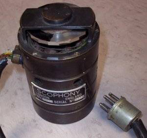
At the end of last year I purchased a 1938 electric motor and mirror drum for our collection from a private collector. Generally speaking, we don’t collect electronic parts; however, this object is an exception for a number of reasons.
As I investigated its history further, I discovered that it had a fascinating background. For one thing, it was a part of the best television made in Britain prior to the Second World War.
What is a high speed scanner motor and how does it work?
Our line scanning motor and mirror is from a 1938 Scophony optical-mechanical projection television set.
In the 1930s, television picture tubes (cathode ray tubes) were mainly small and dim, and only suitable for viewing in low light levels.
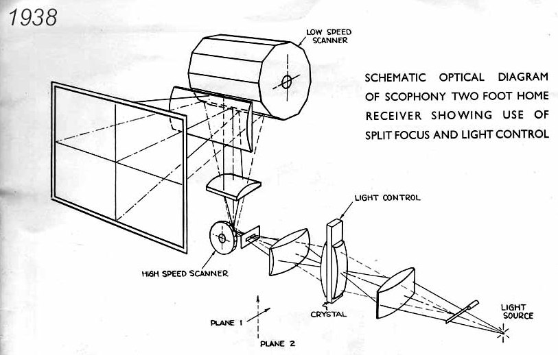
To get a large bright picture, Scophony engineers developed a revolutionary projection system using a high intensity mercury vapour lamp.
This light was then modulated (controlled) by a Jeffree cell, and scanned across the screen by 2 mirror drums, a small high speed one like this to produce the line scan, and a large slow speed unit to produce the frame scan (12 mirrors rotating at 250rpm).
It actually consists of 2 motors running on the same shaft, a standard induction motor to bring the unit up to speed, and a phonic motor (in reality another synchronous motor, but designed to work with high frequencies) which was synchronised to the line pulses of the incoming signal.
The motors turned a 20-sided stainless steel mirror drum (visible at the top of the unit) at 30375 RPM to reproduce live 405 line pictures being broadcast by the BBC.
Sadly, none of the TV sets this motor is designed to fit exist today. The Scophony company no longer exists either.
Who were Scophony?
Scophony was one of the most highly original television manufacturers of the 1930s. Their innovative optical-mechanical television systems produced large screen high-definition pictures for both the home and cinema.
The company operated internationally: in Britain and Germany in the early 1930s, and then in Britain and America in the late 1930s.
The story began with a visit to Germany in 1929 to see television pioneer Dénes Von Mihály. The founder of Scophony, entrepreneur Solomon Sagall, had decided to begin his first venture into television by purchasing the British rights to the Telehor television system from Mihály, founding a company called British Telehor Ltd.
The following year, a small German company was formed and given the name Scophony, while a British subsidiary was established.1 By 1936, this was formed into a public company, Scophony Ltd with the British radio and television manufacturer, EK Cole (Ekco) acting as one of two major investors.
The company’s contributions to television’s technological history have certainly not received the attention they deserve, in part because the Television Committee formed in 1935 made its decisions before Scophony’s technologies had been fully developed, and because no complete Scophony television sets survive today either in museums or private collections.
The most complete Scophony television in existence belongs to our collection and can be seen here in Bradford.
How was the Scophony television scanner used?
This motor was designed to carry out the line scanning (as opposed to frame scanning) in what was praised as the ‘best and brightest’ television set on show at the Radiolympia radio and television industry exhibition in 1938.
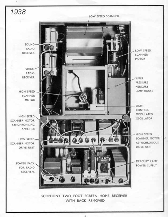
The magnificent Ekco-Scophony model ES104 home receiver boasted a picture 24” wide by 20” high. The screen could fold into the richly veneered cabinet when not in use.
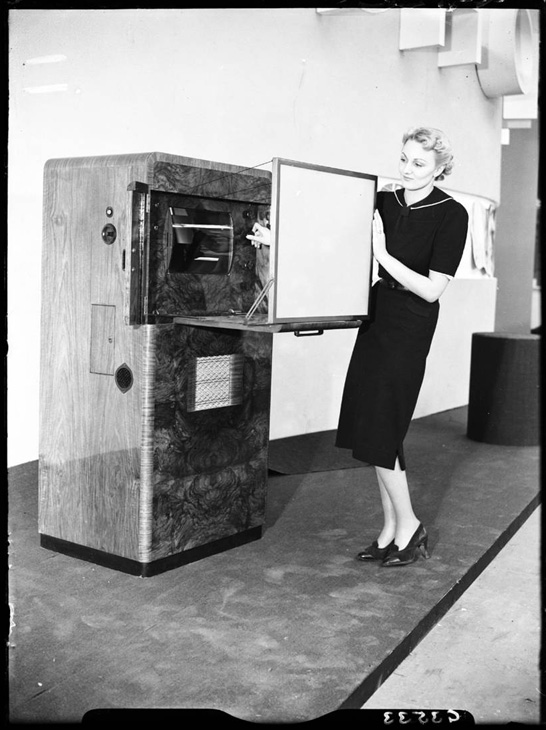
The set cost the equivalent of about £12,000 today—which was about twice as expensive as the finest cathode-ray tube based home receivers. The ES104 had 39 valves and consumed about 1000 watts. Production numbers in 1938 would have been very small, probably in single digits. I have found no evidence to indicate that any ES104 sets were sold.
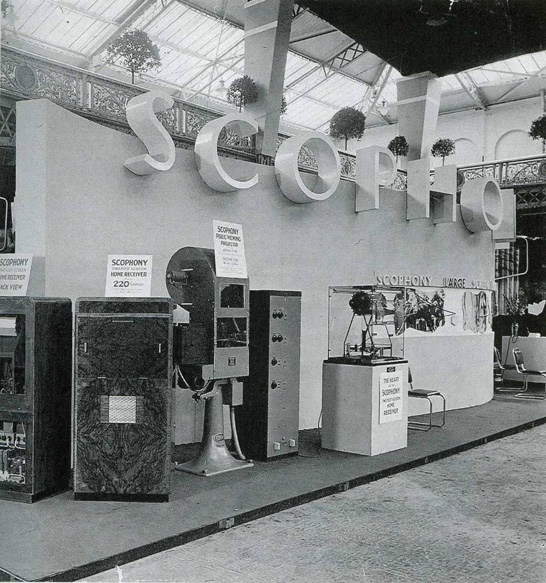
Where did our Scophony motor come from?
Amazingly, our motor came with its original box, which is fairly intact, and it still has its address label. The label states that the motor was sent by van to a Mr E.H. Traub from a Mr G. Wikkenhauser.
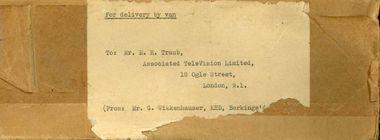
Having written an article3 concerning Ernest H. Traub in 2009, I knew only too well who he was.
A lesser-known figure in the history of British television technology, Traub was a physicist who designed and introduced a novel type of mechanical mirror-drum-based television receiver in 1935 known as the Mihály-Traub scanner—again in collaboration with Dénes Von Mihály, the Hungarian television inventor and engineer based in Germany.
The sender, G. Wikkenhauser, was Gustav Wikkenhauser—also Hungarian—and a mechanical and electrical engineer who worked at Scophony in the 1930s along with Walton, Sieger, Robinson and Lee. In his previous job in Germany, he had worked for Dénes Von Mihály’s company, Telehor Ltd. It was Wikkenhauser who built the two 30 line television receivers Mihály demonstrated at the 1928 Berlin Radio Exhibition.4
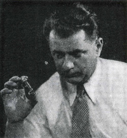
Although there is no date on the box, I suspect that Wikkenhauser sent this motor to Traub in 1938. It seems safe to assume that there was a friendly collaboration going on between Traub’s company, Associated TeleVision, and Scophony (via Wikkenhauser). They had a common colleague in Dénes Von Mihály.
Our Scophony motor could be unique
This motor could very well be the only one left. I’m pleased it will be safely preserved within our collection to complement our other Scophony artefacts.
It was interesting to correspond with the collector who sold it to us, and discover where he had found it—34 miles northwest of London as it turned out…
I found the unit on the local tip in Chesham, Bucks, in about 2002, and purchased it as scrap. It has since been seen at a couple of small displays, at Broadway Baptist Church in Chesham, and at Twyford Waterworks, in Twyford Hants, as well as a picture being on my webpage for some years. It did once make a brief appearance at the BVWS swap meet in Harpenden. As to where it hid in the intervening years, I have no idea, though all sorts of interesting bits used to turn up on Chesham tip!
Our other Scophony artefacts include a collection of documents, news clippings and photographs from the files of Scophony engineer Joshua Sieger. There is also an original Jeffree Cell, and a couple of examples of Scophony advertising literature—a fold-out black and white pamphlet and a colour poster.
Further reading
- Singleton, T The Story of Scophony (London, Royal Television Society, 1988)
1 Burns, R W Television: an International History of the Formative Years (IET, 1988) p252
2 Singleton, T The Story of Scophony (London, Royal Television Society, 1988) p93
3 Baird, I L ‘The Mihály-Traub Scanner’, The Narrow Bandwidth Television Association (NBTVA) Newsletter, 2009
4 Singleton, T The Story of Scophony (London, Royal Television Society, 1988) p21
Fascinating.
Thank you for writing such an informative and well written article.
It’s a story I never knew.
yes very rare it was the best mechanical television ever
Incredible luck finding that scanner ! The Scophony design was remarkable for it’s time, employing a unique “trick” called the ‘Scophony Balance’ to dramatically increase the light output. Scophony Company also built a projector and installed it in a newsreel theatre in London in 1938 where they were able to show live sports events, broadcast by the BBC, on a 12ft x 9ft screen.The laser video projector developed by Dwight-Cavendish Displays in the early 1980’s and subsequently developed into the high-definition projector by Laser Creations Ltd. in the early 1990’s as part of the Eureka “HDTV for Europe” project, used exactly the same scanning and modulation techniques.
Tony, I’d be interested to know what the trick is, and what a “Scophony Balance” is! Purely as a curious member of the public. But I also think it’s important to get as much relevant technical information recorded as possible, while there are still people who remember it.
Things like exact measurements aren’t important, in my opinion, but operating principles, particularly clever or counter-intuitive ones, definitely are. Partly because they might reveal some principle we might use again in the future, partly because it shows the kind of thinking our forefathers had to use, when our modern way of doing things wasn’t available.
Sam. I just noticed your question. The ‘trick’ in the Scophony system was to balance the speed of the moving acoustic wave in the Jeffree cell with the equal and opposite rotation of the polygon mirror doing the line scanning of the image. The Jeffree cell, and it’s modern equivalent, the Acousto-Optic Modulator (AOM), works by a very high frequency transducer vibrating against a compressible medium, water in the case of the Jeffree cell and a crystal (such as quartz, tellurium dioxide or similar) in an AOM. This HF vibration is modulated by the video signal, so varying intensity acoustic wavelets representing the flow of video pixels are induced into the compressible medium and move through it. The varying compressions cause variations in refractive index making a light beam, passing through the medium, bend. The intensity of this bent beam therefore varies according to the video signal. If by reflecting, by a suitably placed mirror, only this bent beam, and projecting it onto a screen by a high-speed rotating mirror, it displays the video signal, in modulated light form, across the screen as a scan line. To successfully project the light beam to show the individual pixels, the light beam had to be reduced in diameter to the same size as one acoustic wavelet, thus reducing the light intensity dramatically. If this was not done, it made a much brighter image but the flow of pixels across the light beam profile blurred together reducing the image resolution. The Scophony Balance ‘trick’ was to arrange the position of the rotating polygon scanner with respect to the AOM such that the angular velocity and direction of its moving wavelets, ie., the pixels, were exactly balanced by the equal and opposite angular velocity of the scanner’s mirror reflecting the beam onto the screen. The pixels were thus frozen onto the screen, the scanning light spot effectively ‘painting’ the flow of pixels onto the screen in a line. This allowed a large diameter light spot to be used, illuminating multiple pixels in the AOM, but still maintaining a high resolution image with high brightness.
Hi Tony, your explanation is almost perfect but I may be misunderstanding one part of your explanation.
Firstly there was no such thing as pixels in analogue TV, but I understand that it is useful to help describe the method, whereby a pixel can be considered as a single modulated wave.
Scophony didn’t actually reduce the light to a spot. The Jeffree cell acted as a diffraction grating, each wave moving through the cell would bend the light according the the video amplitude as you describe. Depending whether positive or negative modulation of the amplitude of these waves was used, a slit or a narrow block was used at the focal point of the light passing through the cell in the X axis (X axis being the axis along which the waves travel in the cell). Thereby the light would either pass around the block the larger the amplitude, or would not pass through the slit, the larger the amplitude. After passing through the slit or around the block, the light would strike the horizontal scanning mirror. As you describe, this was synchronised with the speed of the propagation of the waves moving through the Jeffree cell, such that when they hit the screen, each wave was frozen on the screen illuminating that location in a similar manner that a pixel would.
All of the light from the Jefree cell would be displayed all the time, so that if it could be seen slowed down, a moving image of the horizontal line of light from the Jefree cell would be seen moving across the screen.
Separate X and Y cylindrical lenses were used to focus the light passing through the Jeffree cell, so that the Y focusing would produce the width of line required on the screen and the X focusing would be onto the slit / block, to provide the modulation.
20 years ago I investigated as much as I could about the Scophony system, with a view to making a reproduction of the technique, albeit using modern materials and components at that time. I intended it to work on UK 625 line TV signals. I got as far as obtaining a suitable crystal and making a Jeffree cell using acrylic sheet and bathroom silicone. I obtained a suitable high speed multi faceted mirror from a laser printer, but then things slowed down as I tried to obtain suitable cylindrical lenses at DIY prices. Then I moved due to work and the whole project stalled.
I have sometimes considered whether to try resurrecting it, maybe not completely in the original form. E.g. to use the Jeffree cell as a line store and using a Xenon strobe light source or pulsed LEDs to flash the lines once per horizontal sync pulse (this would need to be delayed to synchronise when the Jeffree cell contains a complete line).
While this would be mechanically much simpler, requiring only a vertical scan mirror drum, I presume that the waves at one end of the cell would be higher amplitude than the other, giving a horizontal degradation of the contrast and brightness. Furthermore, it would not be a true reproduction of the technique. On the other hand further enhancements could be made, e.g. using 3 x Jeffree cells with RGB LEDs.
Yes not an easy project i was looking into the modulation side using crystals and found Heat was a big problem as you can imagine vibrating a solid as high frequencies causes friction fine at tiny voltages but at a few hundred it will boil your liquid away very quickly well thats what i found experimenting ! …i really don’t know how they did it !
I have just come across this page and thought I would add a bit of information as back in the 1980s I worked for Dwight Cavendish, who produced the SD270 laser projector TV. It used 2 argon ion Spectra Physics lasers, one with special end mioors to allow green light from one end and blue from the other. The second identical laser was used to optically excite a dye laser. This was a special type of laser that used a dye pumped at pressure through a very accurate jet and the intense light set up a fluorescence which was red in colour and the cavity used laser principles to generalt a red beam. Each beam of light was around 1 to 1.5 watts in power, but of course condensed in a very small spot. Each colour was modulated by an acousto optic modulator and then passed to the scanning system.
To answer Tony’s question, Scophony is basically an optical system where the light is focussed in two planes by cylindrical lenses. In this way a very small spot of light could be focussed on the hight speed rotating mirrors of the line scanner and then again on to the small mirror of the vertical galvo mirror. A result of this was that there was no focus at all in the imaging system. Where ever you placed a screen the picture was in perfect focus and you could project onto curved surfaces.
The projector required a modified Time Base Corrector, TBC, designed to work backwards. These were common in TV at the time and used to correct for the mechanical variations of video recorders used in studios. The very small variations of the head motor without a TBC would result in the picture waving about from side to side. The TBC stored each line of video and read it out in sync from the genlock signal. On the projector we fed in steady video line by line and used a optical sensor mounted on the spinning mirror assembly to provide the read signal. So as the motor’s servo hunted around the picture was read out with an equal but opposite time difference giving a steady picture. It was interesting to see the effect of this by feeding in raw video, the picture would vawe about several cm on a 10m wide picture. Nothing was required for the vetical scam galvo mirror. The line scan mirror was a precision made mulit faceted polygon mirror, around 30 if memory serves me well.
One big downside was the power consumption, each laser was rated at around 12kW and required around 5 litres of water a minute to keep the laser tubes cool as well as the controlling elecronics. But at the time the only equivalents, the GE light valve and the Eidophor were both smaller and lighter, but neither could produce red to the same level and the light modulation technique used hot oil. This made them suseptable to fast moving video as well as to being moved when hot as the cathode could easily become poisened by oil vapour.
Steve. After the end of the HD-LVP project at Laser Creations Ltd., mainly due to the success of Texas’s DMD chip (our last LVP installation was in Indonesia in 1997), I had to learn to operate and maintain our purchase of the last two Eidophor projectors for an installation in the Philippines in 1998. They actually worked pretty well and produced a good picture, but initial alignment was quite a job, involving setting vacuum pump pressures, oil temperature control, lamp alignment, cathode replacement, and multiple video adjustments like on the old CRT projectors to achieve undistorted, flat field, properly converged images for each of the 3 ‘guns’ (like a CRT projector). It took up to 45 minutes after power-up to achieve a sufficiently low vacuum for the cathodes to be switched on and a picture to appear ! If one of the 3 cathodes failed, it would potentially spell disaster for a show but the makers (Gretag AG in Zurich) had designed in a special control to seal off the cathode to maintain the vacuum chamber so it could be changed, just like putting in a new light bulb, in about 15 seconds.
Steve. You might be interested to know that in our laser-video (LVP) project at Laser Creations, with a view to getting rid of the bothersome dye laser, we used a Krypton laser for the red. Although this produced a horrible image colour balance due to the long wavelength (647nm), I discovered that there was also a weak yellow beam emitted by the laser (I think it was 496nm) and by special laser optics it could be increased to about 10%-15% of the intensity of the main red beam. Thanks to the much higher sensitivity of the eye to this shorter wavelength beam, the overall effect of the mixed beams was a warm red colour not dissimilar to the dye laser’s red. As a result, the dye laser could be eliminated and installations made much more reliable. As for the line scanner, although the original SD270 used a 25 facet polygon mirror, for HD we had a special 36 facet scanner built and capable of 60,000 rpm. This allowed up to 36kHz scanning which was fine for the early HD systems (NHK, 1125/60 and Eureka 1250/50, both interlaced). Completely new electronics was also developed to handle both standard and HD scanners, though both scanners had the same mirror fact detection and line shifting to compensate for errors. Interestingly the Scophony scanner had in addition to the normal motor windings, a ’20-pole Phonic Wheel’ to match the number of facets of the polygon mirror, mounted on the motor shaft, very similar to a modern stepper motor. Line sync pulses were applied directly to the windings around these poles resulting in the phonic wheel, and the corresponding mirror facets, being ‘pulled’ into the correct position to project each video line, thus eliminating the horizontal ‘waving’ of the image and avoiding the need for complex time-base correction circuitry.
This is an amazing find, since the high speed scanner and the Jeffree Cell were the key ingredients of a television system that was many years ahead of its time in the 1930s.
I would love to know more about this unit. The scophony papers say that it could run for about 1000 hours @ 30.000 rpm without needing service. It consists of two motors really, one for getting up to speed quickly and the other to keep it in synchronization.
If one thinks that the Ampex people who developed the quad video recorder in the 1950s had such trouble making their video head motor run at a mere 10.000 rpm for more than 300 hours, it is amazing that this motor could be made in 1938. What kind of bearings were used? can that be seen without taking it apart?
Albert. In 1985 I met John Townsend, the designer and maker of the high-speed Scophony scanner. He told me the scanner had Swiss-made ball-bearings, especially selected for their durability at the very high rotational speed for 405-line TV. To reduce inertia, the mirror-polygon was quite thin. To enable the light spot to fit on this very small area (facet height was cosiderably thinner than it’s width, as can be seen in the photo of the scanner in this article), Scophony engineers developed the “split-focus” method, using cylindrical lenses to separately focus the light beam in the horizontal and vertical planes so the light spot on the scanner’s facets was ‘squashed’ into a thin oval shape, then returned to a normal circular spot by a cylindrical lens after the scanner. You can see the lenses in the drawing at the beginning of this article.